These guns were originally developed for the two ships of the Lord Nelson class, the last of the British pre-dreadnoughts. The mountings and guns intended for those ships were instead used to speed the construction of HMS Dreadnought. As a result, construction on the Lord Nelson class was held up while new guns and mountings were built for them, delaying their completion until 1908. Thus, these last British "pre-dreadnoughts" were actually completed two years after their design had been obsoleted by HMS Dreadnought. Besides their use on capital ships, a further three guns with four spares were mounted as coastal artillery in Belgium during World War I. Constructed of nickel-steel inner A and A tubes, full length wire, B tube and overlapping jacket. The breech bush screwed into the A tube and then were both shrunk and screwed on to collars on the latter. These guns used a mechanically improved breech mechanism of "pure couple" design that was either manually or hydraulically worked. This proved so successful that it was essentially copied in all later designs. 133 Mark X guns were manufactured plus two Mark X* guns, which was to an earlier design with a thinner chase and weighed 448 lbs. (203 kg) less. |
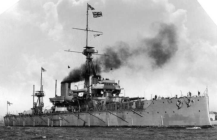
![]() HMS Dreadnought about 1906-1907
|
.
|
Designation | 12"/45 (30.5 cm) Mark X |
Ship Class Used On | Lord Nelson, Dreadnought, Bellerophon, Invincible and Indefatigable classes |
Date Of Design | 1903 |
Date In Service | 1908 |
Gun Weight | Without Breech: 127,232 lbs. (57,711
kg)
With Breech: 129,348 lbs. (58,626 kg) |
Gun Length oa | 556.5 in (14.135 m) |
Bore Length | 540 in (13.716 m) |
Rifling Length | 453.2 in (11.511 m) |
Grooves | 60 |
Lands | N/A |
Twist | Uniform RH 1 in 30 |
Chamber Volume | 18,000 in3 (295 dm3) |
Rate Of Fire
(see Note) |
about 1.5 rounds per minute |
Note: The Rate of Fire
figure given above is found in references for British guns of this caliber,
but "Warrior to Dreadnought: Warship Development, 1860-1905" quotes
Jellicoe's 1906 figures for rates of fire for these guns in gunlayers'
tests and in battle practice and notes that the latter figures corresponded
well to those actually attained by the Japanese at Tsushima:
Gunlayers Test: 2 rounds per minute
|
Type | Bag |
Projectile Types and Weights
(see Note 2) |
APC Mark VI (2crh) - 850 lbs. (386 kg)
APC Mark VIa (4crh) - 859.4 lbs. (389.8 kg) APC Mark VIIa (Greenboy - 4crh) - 854 lbs. (387.4 kg) CPC Mark VIIa (4crh) - 850 lbs. (386 kg) HE Mark IIa (4crh) - 850 lbs. (386 kg) |
Bursting Charge | APC Mark VI - 26.3 lbs. (11.9 kg)
APC Mark VIa - 27.3 lbs. (12.4 kg) APC Mark VIIa - 20.3 lbs. (9.2 kg) CPC Mark VIIa - 80 lbs. (36.3 kg) HE Mark IIa - 106.5 lbs. (48.3 kg) |
Projectile Length | APC Mark VI - 39.7 in (100.8 cm)
APC Mark VIa - N/A APC Mark VIIa - 38.0 in (96.5 cm) CPC Mark VIIa - 48.4 in (122.9 cm) HE Mark IIa - 48.3 in (122.7 cm) |
Propellant Charge | 258 lbs. (117 kg) MD45 |
Muzzle Velocity | 2,725 fps (831 mps) |
Working Pressure | 18 tons/in2 (3,150 kg/cm2) |
Approximate Barrel Life | 220 rounds |
Ammunition stowage per gun
(see Note 4) |
80 rounds |
Notes:
1) Projectile weights from ADM 186/169. The sources below disagree as to muzzle velocity, propellant charge weights and maximum ranges. I have chosen to use those values given in "Jutland: An Analysis of the Fighting." 2) Originally, 4crh projectiles were issued only to the Bellerophon and Indefatigable classes while the others used 2crh. In 1915-16, 4crh were issued to Dreadnought and to the Invincible class. "Greenboys" were issued starting in 1918. 3) AP Cap weights were 34.75 lbs. (15.7 kg) for the Mark VIa and 99 lbs. (44.9 kg) for the Mark VIIa. 4) This is the peacetime outfit which consisted of 24 APC, 40 CP and 16 HE all of which were 2crh. APC and CP were black powder filled while HE was lyddite filled. When the war started the outfit was increased to 110 rounds per gun in most ships. When 4crh were issued to the Invincible class, the outfit was 33 APC, lyddite and black powder filled, 38 CPC and 39 HE, changed by mid-1916 to 44 APC, 33 CPC and 33 HE. A few shrapnel rounds were carried during the war at times. The final outfit for the Invincible class after the war was 77 APC, shellite filled, and 33 CPC. The Indefatigable class carried a peacetime outfit of 24 APC, 28 CPC, 28 HE and 6 shrapnel. The initial war outfit was 33 APC, 38 CPC and 39 HE, later changed to be the same as the Invincible class. |
Elevation | With 850 lbs. (386 kg) AP Shell 2crh |
Range @ 13.5 degrees | 16,450 yards (15,040 m) |
Elevation | With 859 lbs. (389.8 kg) AP Shell 4crh |
Range @ 13.5 degrees | 18,850 yards (17,236 m) |
Range @ 16 degrees | 20,435 yards (18,690 m) |
Range @ 45 degrees
Coastal artillery |
about 25,000 yards (22,860 m) |
Elevation |
|
|
|
0.54 degrees |
|
|
|
3.0 degrees |
|
|
|
6.1 degrees |
|
|
|
11.8 degrees |
|
|
|
20.7 degrees |
|
|
|
40.1 degrees |
|
|
|
Note: This data is from a mathematical study published in a "Warship Volume X" article. As such, it may not accurately reflect the actual performance of these guns. It should also be noted that the performance given for elevations of 20.7 and 40.1 degrees would apply only to weapons used as coastal artillery. |
Range |
|
|
0 yards (0 m) |
|
|
10,000 yards (9,144 m) |
|
|
Note: This data is from "British Battleships of World War Two" for an uncapped AP shell striking a plate at 90 degrees, i.e., with the axis of the shell perpendicular to the face of the plate. A capped shell would show about 10 to 20% improvement at low velocities and about 30 to 50% improvement at high velocities. |
Range |
|
7,600 yards (6,950 m) |
|
Note: Data from "British Battleships: 1860 - 1950" and may reflect the performance of an APC projectile. |
In a Memorandum to the Controller dated 24 October 1910, it was stated that 12 inch (30.5 cm) APC shells striking at any angle over 20 degrees were unlikely to penetrate even 4 inches (10.2 cm) of KC armor (face hardened) and were likely to breakup at angles of 30 degrees when striking 6 inches (15.2 cm) of KC armor. Thus, it can be seen that the poor performance of British shells at Jutland (Skagerrak) cannot have been a surprise to the Royal Navy. Surprisingly, the memo does not suggest that the shells be improved, but instead urges that these thicknesses of armor be considered for future ship designs, as if it was expected that enemy shells would perform as poorly as did their own. |
Designation
(see Note 1) |
Two-gun Turrets
Lord Nelson (2), Dreadnought (5), Bellerophon (5), Indomitable (4) and Inflexible (4): BVIII (Vickers) Invincible: (2) BIX (Vickers) and (2) BX (Elswick) Indefatigable (4): BVIII* (Vickers) |
Weight | 450 - 500 tons (457 - 508 mt) |
Elevation
(see Note 2) |
Ships: - 3 / +13.5 degrees
Coastal Artillery: -5 / +45 degrees |
Rate of Elevation | 3 degrees per second (?) |
Train
(see Note 3) |
Forward and Aft Turrets: about -150
/ +150 degrees
Beam Turrets: about +30 / +150 degrees Q Turret: about +30 / +150 degrees on either side |
Rate of Train | BIX and BX: 4 degrees per second
Others: N/A |
Gun Recoil | N/A |
Loading Angle | Any |
Notes:
1) The BVIII* mountings on the Indefatigable class differed in that the gunshields were of modified shape and structure in an effort to improve protection. The BIX and BX mountings on Invincible were interesting in that they were electrically powered by 200 Vdc from four 200 kW steam generators and 100 kW oil motor/generators within the ship. These mountings proved unsatisfactory and were constantly breaking down during their active service life. As a result, they were converted to all hydraulic power prior to the start of World War I. 2) These mountings were reworked during World War I to increase their maximum elevations to +16 degrees, a rather costly operation for the small increase in range thus achieved, which was less than 1,600 yards (1,460 m) at new gun velocities. 3) The Invincible class had staggered amidships mountings intended to allow them to shoot across the ship as well as directly forward and directly aft. However, gunnery trials showed that the blast damage from such firings was unacceptable and the actual firing arcs were restricted to approximately the figures given above. At the Falklands battle, Invincible fired cross-deck with both P and Q turret but this dazed and deafened the gun-layers, trainers and sight setters as well as causing blast damage to the deck. P turret reported that the trainers had to be replaced constantly during the battle as they were too dazed to function properly. After the battle, cross-deck firing was ruled out except in cases of emergency. 4) These mountings differed from earlier ones in that projectiles and propellants were rammed directly from the main hoisting cage into the gunloading cage without tipping out into an intermediate position. This made for a simpler transfer but slowed the loading cycle as the main cage could not descend until the transfer had taken place. 5) Surviving battlecruisers had 1" (2.54 cm) armor plates added to their turret roofs following Jutland (Skagerrak). 6) Battle experience showed that British turrets in general were inadequately protected, especially on these early 12" (30.5 cm) models. Problems included the lack of gunport shields, which meant that splinters and blast could easily penetrate into the working areas. There were also large gaps between the base of the gunhouse and the top of the barbette, leaving an area of reduced protection. The sighting ports on top of the turrets were of an open design, which allowed both gunsmoke and sea spray to enter into the gunhouse as well as causing considerable discomfit to the crewmembers whose job it was to peer through these ports at the target. These sighting ports and the turret rangefinders also projected up above the turret roof, which unintentionally turned them into deadly shell traps. Finally, the sloping front roof of these turrets meant that the angle of incidence for incoming shells was less than that for a flat roof, which increased the chance of a penetrating hit. |
26 December 2008 - Benchmark
30 January 2009 - Added comment regarding
breech mechanism
31 December 2011 - Added information about
ammunition outfits in battlecruisers
11 March 2012 - Added notes about BVIII*
mountings and loading transfers