5"/38 (12.7 cm) Mark 12
Pictures
Updated 25 October 2012
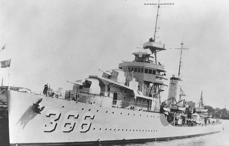
USS Drayton DD-366 during the late 1930s
These are open-back shield pedestal mounts,
a variation of the Mark 21 mounting
Note the bulge on the left side of the
mounts, which was needed to accommodate the fuze setting mechanism
U.S. Naval Historical Center Photograph
# NH 67725
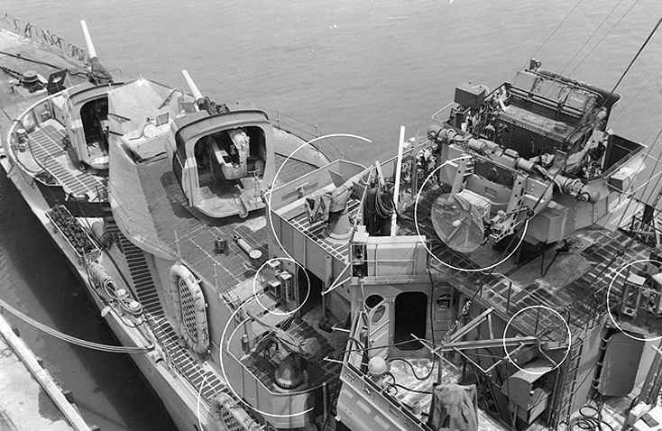
Bow of USS Mahan DD-364 in June 1944
Another view of the Mark 21 open-back
shield pedestal mounts. Note the groove in the deck of Mount #2.
This was to allow a path for ejected cartridge cases when the gun was at
high elevations. The later base ring mounts had the gun mounted a
few inches higher and so did not need this groove. Note the Mark
33 director and its newly added radar and the non-slip tread material patterns
on the decks.
Also note the large "sprayshield" around
Mount 52. This shield was actually meant to protect the gun crew
on the lower deck from the blast from the upper gun. Later destroyers
with enclosed gunmounts did not need this extra protection and so do not
have these shields.
Detail from U.S. Naval Historical Center
Photograph # 19-N-67752
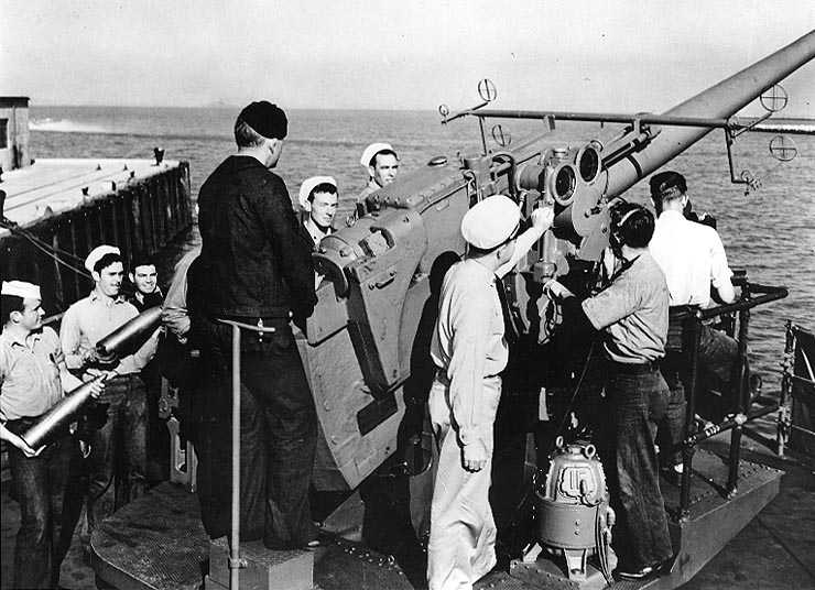
No. 3 gun on USS Shaw DD-373 in July 1942
This is a Mark 21 pedestal mounting.
Note the three circular dials that the officer is pointing to. These
are "follow the pointer" indicators which are used to show the sight angle
(superelevation) (RH glass face dial), deflection angle (bearing) (LH glass
face dial) and the range (bottom metal face dial). Inside each of
the two glass-face dials are two smaller dials - an inner disc dial mounted
on a synchro motor shaft and an outer ring dial inscribed with a scale.
The inner disc dial synchro motors were operated from the fire control
computer and showed the desired sight angle and deflection angle as calculated
by the computer while the outer ring dials showed the current sight angle
and deflection angle of the gunsights. The bottom dial is the range
indicator with the black slot on the right being the readout location which
shows the range in yards. The range dial and the sight angle dial
are geared together. The enlisted man with the head phones is a "sight
setter" whose job was to ensure that the two dials in each indicator were
in line with each other before the gun was fired in automatic mode (which
is where the command "match pointers and shoot" comes from). He did
this by turning two hand cranks, one which adjusted the sight angle and
range dials and the other which adjusted the deflection angle dial.
Turning these hand cranks also moved the prisms in the gunsights used by
the trainer and pointer such that, when the pointers were matched, their
crosshairs should be on the target. In local control, the sight setter
was directed by the mount captain as to the proper settings to be used.
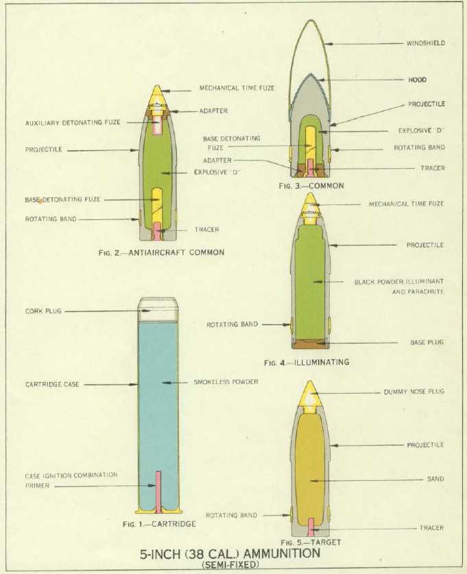
The drill projectiles being held by the two sailors on the left are of interest. The major difference from the 5"/38 (12.7 cm) Mark 12 and its AA predecessor, the 5"/25 (12.7 cm) Mark 10 was its use of semi-fixed (separate) ammunition rather than fixed ammunition. Other interesting features in this photograph are the prominent open sights above the gun and the electric rammer/counterweight at the breech end of the weapon.
U.S. Naval Historical Center Photograph # NH 80-G-22246
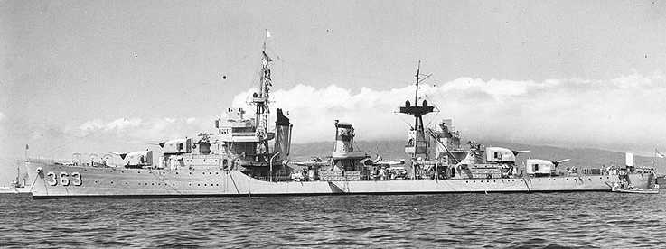
USS Balch DD-363 in April 1939
This was one of the few ships to use the
SP Mark 22 mountings. SP weapons were deemed acceptable on these
destroyers as they were large enough to mount two 1.1"
(28 mm) quadruple mounts, one forward of the bridge and the second
one on the after superstructure just in front of Mount 53. Note the
second director on the aft superstructure and the stowage for torpedo reloads
at the base of the second stack. The Porter (DD-356) class, of which
Balch was a member, were the only US destroyers so equipped with both items.
However, both of these plus the mainmast and Mount 53 were removed early
in the war as weight compensation for additional light AA and radar.
Later, some of these ships had all of their 5" (12.7 cm) SP armament replaced
with five 5" (12.7 cm) DP weapons and their one remaining director upgraded
to the Mark 37 GFCS.
U.S. Naval Historical Center Photograph
# NH 97951

USS Phelps DD-360 in November 1942
A good close up of the Mark 22 mounts
U.S. Naval Historical Center Photograph
# NH 19-N-38915
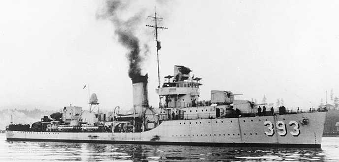
USS Jarvis DD-393 in 1937
This destroyer had two Mark 30 Mod 1 mounts
on the bow and two Mark 21 mounts on the stern
U.S. Naval Historical Center Photograph
# 67842
USS Blue DD-387 in April 1942 showing her
bow Mark 30 mountings
Note the Mark 33 Director on top of the
superstructure
Detail from U.S. Naval Historical Center
Photograph # 19-N-29229
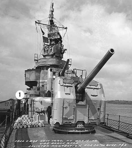
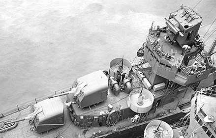
Mark 30 single mounts on USS Arron Ward
DD-483 in May 1942
Note 5" (12.7 cm) propellant canisters
on the left and Mark 37 FCS with "FD" Radar
U.S. Naval Historical Center Photograph
# 19-N-30722

Mark 38 twin mounts on USS O'Brien DD-725
in August 1961
Note Mark 11 Hedgehog
projectors on either side of the bridge
U.S. Naval Historical Center Photograph
# NH 103018
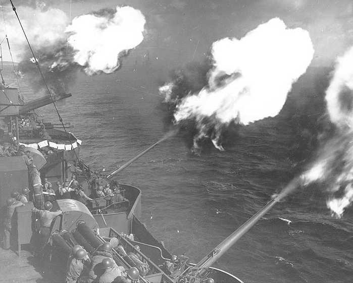
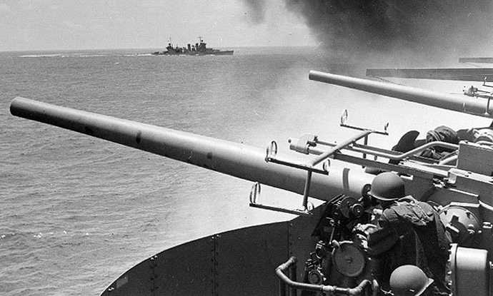
USS Wichita CA-45 firing at Saipan on 26
June 1944
These are Mark 21 or possibly Mark 24
pedestal mountings
U.S. Naval Historical Center Photograph
# 80-G-238240
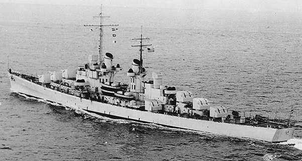
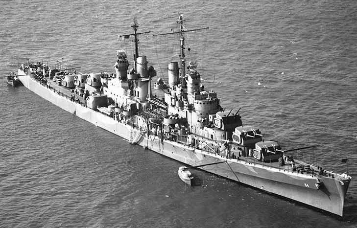
USS Atlanta CL-51 on trials in 1942 showing
seven of her eight 5"/38 (12.7 cm) Mark 29 twin mountings
Note the wing or broadside mounting, which
was installed only on the first four ships of this class
U.S. Naval Historical Center Photograph
# NH 57453
Picture courtesy of Preston Cook and USS
Atlanta Website
Another Atlanta-class light cruiser, this
one USS San Juan CL-54 in June 1942
U.S. Naval Historical Center Photograph
# 19-N-31525
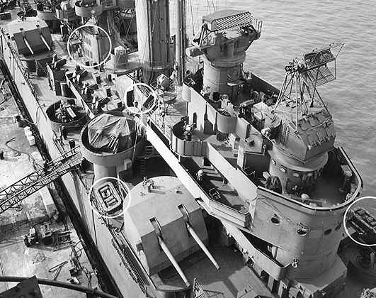
USS Mobile CL-63 in July 1943
Good overhead view of twin 5"/38 (12.7
cm) Mark 32 mountings
Note the Mark 34 (left) director with
Mark 8 radar antenna and Mark 37 director with Mark 4 radar antenna
Detail from U.S. Naval Historical Center
Photograph # NH 98169
5"/38 (12.7 cm) Mark 21 single mountings
aboard USS Yorktown CV-5 during Battle of Midway
The cruiser in the background is USS Astoria
CA-34
U.S. Naval Historical Center Photograph
# 80-G-312019
Good overhead view of 5" (12.7 cm) Mark
24 pedestal mounting on USS Bennington CV-20 in 1944
The gunsights are being aligned by utilizing
a batten board. The long vertical stripes on the batten board are
used to adjust the gunsights such that they remain in parallel with the
barrel as it elevates.
Photograph used here by permission of
USS
Bennington website
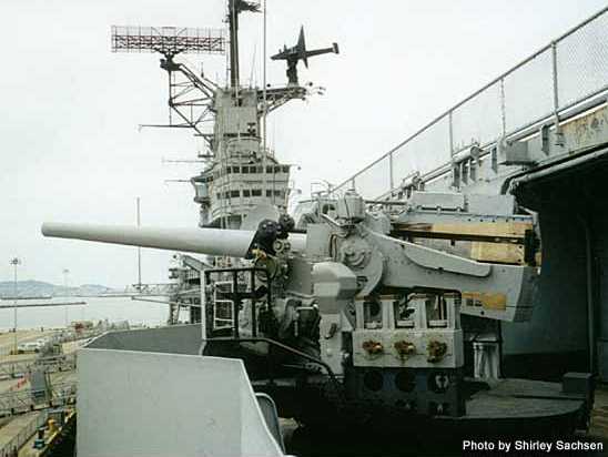
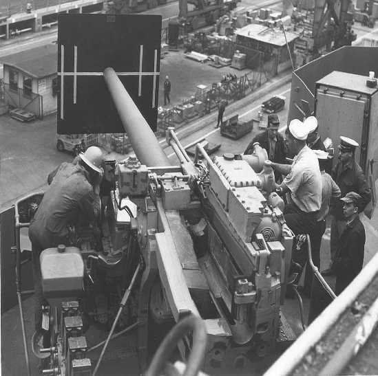
5"/38 (12.7 cm) Mark 24 pedestal mount on USS Hornet CV-12
Note the Mechanical Fuze Setter on the side of the gun platform. These were installed on those mounts lacking integral hoists and were used to set the time fuzes on AA projectiles. Up to three projectiles could be inserted nose-down into the slots on this machine. At the bottom of each slot there is a nose cup with a pawl that engages a lug on the projectile's time fuze ring. The Fuze Setter crewman watches a dial on the Mechanical Fuze Setter that has two pointers and a scale representing fuze time in seconds. The Fire Control System, such as the Mark 37 GFCS, moves the first pointer, which represents the calculated fuze setting needed to engage the target aircraft. The Fuze Setter crewman then rotates a control wheel on the Mechanical Fuze Setter until the second pointer matches the first pointer (again, this is where the command "match pointers and shoot" comes from). The Mechanical Fuze Setter rotates the nose cups per the position of the second pointer, thus moving the time fuzes on the projectiles to the desired setting. Having three slots allows enough time for each successive shell to be set to the proper time setting before the shell man picks it out of the machine and places it into the loading tray on the gun. This method of fuze setting also allows the time fuzes to be continually updated by the Fire Control System until the moment they are plucked from the machine, thus ensuring the best possible setting for each individual shell (a "deadtime" to allow for the interval between when a shell is plucked from the Mechanical Fuze Setter and when it is fired out of the gun is automatically included in the fire control calculations).
Photograph copyrighted by Shirley Sachsen and used here by her kind permission
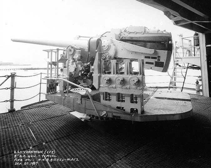
5"/38 (12.7 cm) Mark 21 on USS Yorktown
CV-5 just prior to commissioning
This is either a Mod 1 or a Mod 16
U.S. Naval Historical Center Photograph
# 19-N-17439

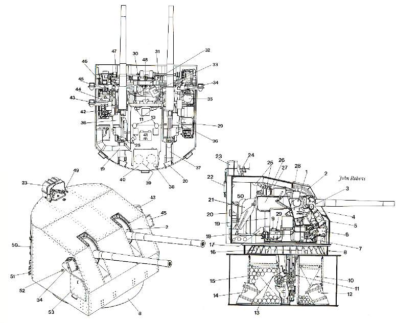
Fuze-setting mechanism for mountings having
projectile hoists
Crewmen in the handling room place projectiles
nose-down into the cups with the fixed lug inserted into the V-groove slot.
As the projectile travels up the hoist, the fuze-setter chain moves the
sprocket which rotates the the inner socket. The pawls on the inner
socket engage the time ring lug, rotating the fuze to the proper setting
as determined by either the automatic fire control system or by a crewman
manually turning a handwheel.
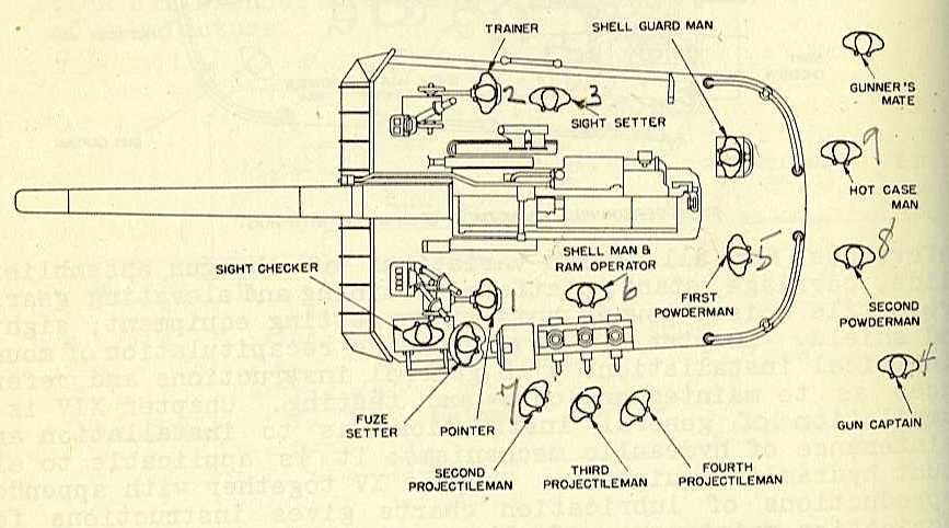
Crew positions for a typical open 5"/38
(12.7 cm) mount lacking integral hoists such as used on carriers
Note the Mechanical Fuze Setter and its
operator on the left of the platform
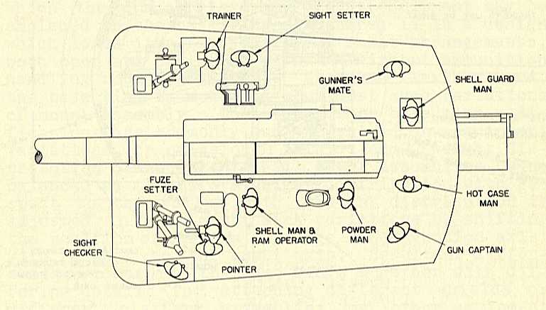
Crew positions for a typical enclosed base-ring
Mark 30 mountings with integral hoists
Time fuzes are set in the shell hoists
for this type of mounting, eliminating the need for a Mechanical Fuze Setter
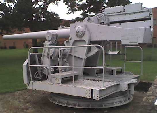
One of two 5"/38 (12.7 cm) Mark 37 Mounts
now at Lancaster Elementary School in Lancaster, Kentucky
These were simplified mountings used to
arm merchantmen and auxiliaries
Note the narrower working platform of
the Mark 37 mount when compared to the Mark 24 and Mark 30 open mounts
and the lack of a fuze setter. The two mountings on display at this
school are missing the rear portion of the platform. A more complete
example of the Mark 37 mounting is on display at the National
Museum of the Pacific War located at Fredericksburg, Texas, USA.
Photograph copyrighted by Hank
Murphy and used here by his kind permission
USS Valley Forge CV-45
Twin 5"/38 (12.7 cm) Mark 32 mounts during
target practice in November 1949
Note the Skyraiders, a versatile warplane
that served for twenty years in the USN
U.S. Naval Historical Center Photograph
# NH 70276

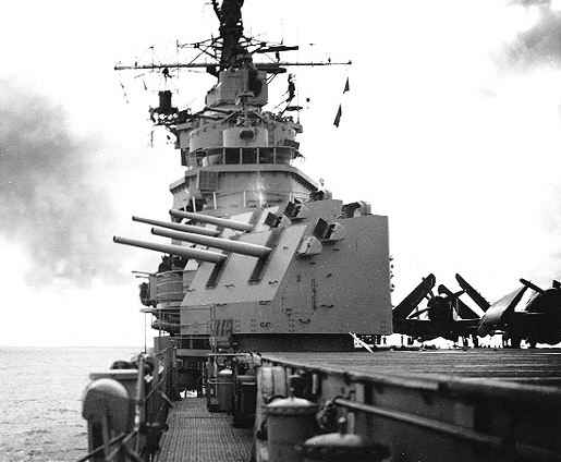
USS Missouri BB-63
Twin 5"/38 (12.7 cm) Mark 28 mounts in
action during a night gunnery practice in August 1944
U.S. Naval Historical Center Photograph
# 80-G-K-4550

Replacing a gun barrel on USS Taussig DD-746
in 1969
The bayonet-joint connecting the gun barrel
to the receiver group on this weapon meant that such changeouts could be
rapidly and easily accomplished without dismantling the gun house or dismounting
the gun. It takes about 8 hours to change out one gun.
U.S. Naval Historical Center Photograph
# USN 1143149
(National Archives Photograph # 428-N-1143149)
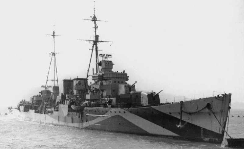
HMS Delhi after being refitted in the USA
with five 5"/38 (12.7 cm) Mark 30 mounts and two Mark 37 GFCS
Note that the Mark 37 directors are equipped
with British radars
Photograph courtesy of Steve Johnson of
Cyberheritage
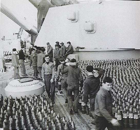
Removing 5" (12.7 cm) projectiles from USS Missouri (BB-63) in 1950

Italian Impavido (D-570) guided missile
destroyer in May 1983
An example of how the 5"/38 (12.7 cm)
Mark 12 continued to be used on new construction long after the end of
the war
U.S. Navy Photograph No. DN-SC-92-01098