United States of America
6"/47DP (15.2 cm) Mark 16
Updated 21 July 2009

Essentially the same 6"/47 (15.2 cm) Mark 16 gun as used for the previous Cleveland and Brooklyn classes, but used in a mounting with better shell handling and loading equipment.  For the first time ever in any navy, a gun mount larger than 5" (12.7 cm) had training and elevation rates fast enough to be truly called "Dual Purpose."  And, unlike all previous US 6" (15.2 cm) guns, these could load at any angle, greatly enhancing their use in the AAA role.  Unfortunately, these ships were completed too late for World War II and were rapidly made obsolete by AA missiles.  The 6"/47DP (15.2 cm) mountings can be considered as being the mechanical prototypes for the much more successful 8"/55 (20.3 cm) Mark 16.

These guns had a long development cycle with bursts of activity followed by periods of neglect.  The officers of BuOrd had high hopes for these weapons, but they were continually frustrated in finding a home for them.  Work began in 1937 as the main guns for a new class of cruisers limited by treaty to 8,000 tons.  This project was halted in 1940 with the failure to produce an acceptable 8,000 ton design for this cruiser.  An attempt in 1940 to get them onto what became the Montana class battleships died when BuOrd's own study showed that the 5"/38 (12.7 cm) and 5"/54 (12.7 cm) designs were better choices.  In 1941 the guns were revived yet again, as the introduction of new, higher performing aircraft showed a corresponding need for a higher performance AAA weapon.  However, the entry of the US into World War II meant that existing ships and weapons received priority and development of the new 6" (15.2 cm) was correspondingly slowed.  The design was not finalized until 1943 and USS Worcester did not commission until 1948, long after the war was over.

These guns did not prove reliable in service, possibly because of the high rate of fire and need for any-elevation loading.  Another contributing cause was that they used a dual projectile hoist system - one for AP and one for HC/AA shells - which proved to be a source of jamming.  And the dual-purpose performance came at a steep price in weight, with these twin turrets weighing about 20% more than the triple turrets used on the previous Cleveland class.  In this regards, it should also be noted that the late-war equivalent 5"/38 (12.7 cm) armed Atlanta class AA cruisers carried the same number of guns on less than half the displacement of Worcester.  In other words, two Atlantas carrying a total of 24 of the excellent 5"/38 (12.7 cm) guns could be built for less tonnage than one Worcester carrying half as many guns, albeit more powerful ones.

Constructed of monobloc autofretted barrel with liner secured to the housing by a bayonet joint.  Mark 16 Mod 1 differed from Mod 0 in having a tapered liner.  All used a semi-automatic vertical sliding breech block accommodated in the housing.  There was a 0.5 in (12.7 mm) ring attachment at the muzzle.

There were plans made to replace the twin turrets on new ships with a triple fully automatic DP mounting similar in concept to those for the 8"/55 (20.3 cm) Mark 16.  These were expected to be able to fire 20-25 rounds per minute per gun compared to 12 rounds per gun in the twin mountings.  This project was cancelled at the end of the war.

WNUS_6-47DP_mk16_Worcester_pic.jpg

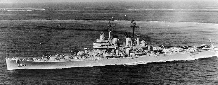
USS Worcester CL-144 in June 1950
Note the fire control radar directly behind Turret III, the amidships director and that Turrets II and V were not superfiring
U.S. Naval Historical Center Photograph # NH 81832

.
Click here for additional pictures
.
.
Gun Characteristics
.
Designation 6"/47DP (15.2 cm) Mark 16
Ship Class Used On Worcester (CL-144) class
USS Mississippi (AG-128) (gunnery training ship)
Date Of Design 1943
Date In Service 1948
Gun Weight N/A
Gun Length oa 300.0 in (7.620 m)
Barrel and Bore Length 282.3 in (7.169 m)
Rifling Length 238.3 in (6.053 m)
Grooves N/A
Lands N/A
Twist Uniform RH 1 in 25
Chamber Volume 1,470 in3 (24.1 dm3)
Rate Of Fire 12 rounds per minute
Note:  The exterior of the gun was sprayed with zinc for 25.5 in (64.8 cm) starting 20.25 in (31.4 cm) from the breech end.  The bore was chrome plated 0.0005 in (0.013 mm) deep for 246.0 in (6.248 m) from the muzzle.
.
Ammunition
.
Type Separate
Projectile Types and Weights
(see Note 1)
AP Mark 35 Mods 1 to 11 (super heavy) - 130 lbs. (59 kg)
HC Mark 39 Mod 0 - 105 lbs. (47.6 kg)
Illum Mark 41 Mod 0 - 110.0 lbs. (49.9 kg)
Bursting Charge AP Mark 35 - 1.95 lbs. (0.9 kg) Explosive D
HC Mark 39 - 14.09 lbs. (6.4 kg) Explosive D
Projectile Length AP Mark 35 - 27 in (68.6 cm)
HC Mark 39 - 30 in (76.2 cm)
Illum Mark 41 - 30 in (76.2 cm)
Cartridge Case Type, Size and Empty Weight
(see Note 4)
Mark 4 - Brass, 152 x 970 mm, 28.2 lbs. (12.8 kg)
Mark 4 Modified - Brass, 152 x 635 mm, N/A
Propellant Charge
(see Note 5)
Full Charge - 33 lbs. (15.0 kg) SPD or SPDN
Full Flashless Charge - 34 lbs. (15.4 kg) SPCG

Reduced Charge - 21 lbs. (9.5 kg) SPDN
Reduced Flashless Charge - 22 lbs. (10.0 kg) SPDF

Muzzle Velocity Full Charge - New Gun
   AP Mark 35 - 2,500 fps (762 mps)
   HC Mark 39 - 2,665 fps (812 mps)

Reduced Charge - New Gun
   AP Mark 35 - 2,050 fps (625 mps)
   HC Mark 39 - 2,225 fps (678 mps)

Working Pressure 18.5 tons/in2 (2,910 kg/cm2)
Approximate Barrel Life
(see Note 2)
750 - 1,050 rounds
Ammunition stowage per gun 403 rounds
Notes:

1) The HC Mark 39 Mod 0 projectile was a half-caliber longer than those rounds used for earlier guns.  This projectile body was a "universal" type designed such that it could be loaded with HC, WP, Illumination or Window fillers.  The HC rounds could be used with Point Detonating (PD), Mechanical Time (MT) or with proximity (VT) nose fuzes.  When used with PD fuzes, they were considered to be HC rounds while those with MT and VT fuzes were considered as AA rounds.

2) The sources listed below differ as to the barrel life.  I have chosen to use the figure given in "World Naval Weapon Systems 1991/1992."  A 105 lbs. (47.6 kg) HC round fired at 2,665 fps (812 mps) was equivalent to 0.71 ESR, the 130 lbs. (59.0 kg) Target round at 2,050 fps (625 mps) to 0.21 ESR and the 105 lbs. (47.6 kg) Target round at 2,300 fps (701 mps) was 0.21 ESR.

3) The cartridge cases were sealed with cork plugs which extended about 2.5 in (6.4 cm) past the mouth of the case.

4) Mark 4 was used for Full Charges while the Mark 4 Modified was used for Reduced Charges.

5) Some SPD cartridges had flashless pellets added which gave them a "reduced" flash.

.
Range
.
Elevation
With 130 lbs. (59 kg) AP
Striking Velocity
Angle of Fall
3.3 degrees
6,000 yards (5,490 m)
1,799 fps (548 mps)
4.15
6.5 degrees
10,000 yards (9,140 m)
1,428 fps (435 mps)
9.7
14.5 degrees
16,000 yards (14,630 m)
1,129 fps (344 mps)
24.3
22.3 degrees
20,000 yards (18,290 m)
1,102 fps (336 mps)
36.6
44.5 degrees
26,000 yards (23,770 m)
1,209 fps (369 mps)
58.1
47.5 degrees
26,118 yards (23,881 m)
---
---
Elevation
With 105 lbs. (47.6 kg) HC
Striking Velocity
Angle of Fall
46.6 degrees
23,483 yards (21,473 m)
---
---
AA Ceiling
@ 78 degrees
48,000 feet (14,630 m)
---
---
Note:  Time of flight for AP Shell with MV = 2,500 fps (762 mps)
   10,000 yards (9,140 m): 16.2 seconds
   20,000 yards (18,290 m):  44.7 seconds
   26,000 yards (23,770 m):  77.3 seconds
.
Mount / Turret Data
.
Designation Two-gun Turrets
   Worcester (6)
   Mississippi (1)
Weight  208.5 tons (212 mt)
Elevation -5 / +78 degrees
Elevation Rate 14.8 degrees per second
Train about +150 / -150 degrees
Train Rate 25 degrees per second
Gun recoil 21 in (53 cm)
Loading angle Any Angle
Notes:

1) These mountings had the guns individually sleeved.  RPC was fitted as completed.  The train and elevation rates of these mountings were similar to those for the 5"/38 (12.7 cm) twin DP mountings.

2) This turret had one projectile ring, but the ring had two tiers, one for each shell flat.  Each tier was set up to stow 288 projectiles.  In addition, fixed stowage capacity was 106 projectiles at the upper level, and 124 at the lower.  Some sections of the upper flat were hinged so that they could be swung out of the way when the lower flat was in use.  Shells were stowed on three decks of the rotating structure with the hoists running from from the two upper levels and the live shell ring on the uppermost.  Both shell and cartridge hoists ran directly to the gunhouse.  The projectile hoists brought the projectiles to a point adjacent to the gun slide.  The projectile was manually loaded into the projectile tray and the powder case was mechanically loaded into the powder-case loading tray.  The projectile tray drive unit then drove the projectile tray and fuze setter head aft towards the rear of the slide.  The powder-case crosshead, which was mechanically linked to the case-stop drive, engaged the base of the case in the powder-case loading tray.  The case stop drive for most of this operation was set to function as a braking unit; thus the projectile tray drive unit during most of its stroke aft drove the projectile and powder case against the braking effort, exerted through the powder-case crosshead, of the case-stop drive unit.  This kept the projectile’s nose firmly inside the fuze-setter pot during this movement aft and the nose fuze was set during this operation.  At the end of this stroke the complete round was delivered to the traverse carriage loading tray in the traverse carriage, which moved transversely across the slide.  The traverse carriage was driven by a drive unit near the rear of the slide and had two trays, one for loading the next complete round and the other to receive the empty cartridge after the gun fires.  The traverse carriage had two positions; one with the empty case carriage behind the gun breech and the other with the complete round carriage behind the gun breech.  Rammers were attached to the end of the slides.

3) These turrets were powered by electric motors with hydraulic drive gears.  Training motors were 200 HP while the elevation motors for each gun were 15 HP.  Each gun had a 15 HP motor which operated both the breech mechanism and the rammer, which was attached at the rear of the slide.  Each shell hoist was powered by a 5 HP motor and each cartridge hoist was powered by a 10 HP motor.  The live shell ring was powered by a 10 HP motor.

4) Manning was twenty-one crewmembers in the gunhouse, ten in the turret officer’s booth and eleven in the gun house.  This was made up of eleven turret controlmen, three gun-laying operators, three gun operators, two hot-case men, and two projectile loaders.  The eleven turret controlmen were organized as follows:  The turret officer, the turret captain, the talkers, the radar operators, computer operator, and two sight setters.  The checker, a member of the crew in training operations only, does not man his station in battle action.  The three gun-laying operators are the right and left pointers, and the trainer.  The three gun operators are the two gun captains - one for each gun - and the gunner’s mate repairman, stationed in the turret officer’s booth and charged with performing general maintenance of the gun control equipment.  The two projectile loaders were located at the loading tray, one for each gun.  They operated the fuze setting indicator-regulator when the fuze setting system is in manual control.  The two hot-case men were located one on the outboard side of each gun near the case ejector.  At the lower levels, the same crew of seven operates on either the upper or the lower ammunition flat.  This consists of a petty officer in charge and one projectile loader and two passers for each hoist being served.  The loaders merely shove projectiles into the hoists, which start automatically when loaded.  The passers keep the loaders supplied; they also operate the projectile ring as required.  At the powder-handling room level, four powder-passing scuttles admit powder cases from the magazine.  A crew of nine operates in the powder-handling room with six powder passers taking the charges from the scuttles to the powder hoists, two powdermen operating the scuttles at the foot of the hoists, and a petty officer in charge.

.
Data from
"Naval Weapons of World War Two" by John Campbell
"US Cruisers:  An Illustrated Design History", "US Naval Weapons" and "The Naval Institute Guide to World Naval Weapon Systems 1991/1992" all by Norman Friedman
"Round Shot to Rockets:  A History of the Washington Navy Yard and the United States Naval Gun Factory" by Taylor Peck
"Cruisers of World War Two" and "Battleships of World War Two" both by M.J. Whitley
---
"Naval Ordnance and Gunnery:  Volume 1, Naval Ordnance 1957 Edition" NavPers 10797-A
"U.S. Explosive Ordnance:  Ordnance Pamphlet 1664 - May 1947" by Department of the Navy
---
Special help from Leo Fischer and Gene Slover
Page History

27 November 2008 - Benchmark
21 July 2009 - Added to Mount / Turret notes on ammunition handling and manning