Japan
40 cm/45 (15.9") Type 94
Actual Size 46 cm (18.1")
Updated 08 January 2013

The 46 cm/45 (18.1") cannons used on the Yamato class were the most powerful guns ever installed on a battleship.  While closely matched by the USA 16"/50 Mark 7 at long ranges, in a close-range engagement the penetration power of this weapon was unsurpassed.  The muzzle blast is said to have been able to rip the clothes off personnel who were standing too close when the guns were fired, but this story is probably apocryphal.

These guns were officially designated by the Japanese as "40 cm/45 Type 94" (15.9 inch) in an effort to hide their actual size, which was a closely-guarded secret until after the end of World War II.

The Yamato is known to have fired at enemy ships on only one occasion.  This was at the Battle off Samar in October 1944 against the U.S. Taffy 1 and Taffy 3 escort carrier groups, with rounds possibly hitting USS Gambier Bay (CVE-73).  The Musashi is known to have fired her guns in anger only once when she fired "sankaidan" (incendiary shrapnel) anti-aircraft shells during the Battle of the Sibuyan Sea in October 1944.  One of these reportedly exploded in the barrel, disabling the gun.

A total of 27 guns were produced, with the first one being completed in March 1938 and tested at the Kamegakubi proving grounds.  Eighteen of these guns were lost with Yamato and Musashi, two test guns at Kamegakubi were demolished in November 1945 in accordance with the general disarmament orders of the U.S. Army and the remaining seven were found in various stages of completion on the beach in a cove north of Kamegakubi.  See picture on the additional photographs page link below.  Five of these remaining guns were destroyed while the last two were taken to Dahlgren Proving Grounds in Virginia, USA, for testing.  These were reportedly cut up for scrap sometime during the 1950s.  Two partially completed turntables intended for Shinano were also captured and later destroyed.

These guns had an unusually complex construction, perhaps reflecting the difficulty in manufacturing such a large caliber.  The A tube, designated as 2A, had the 3A tube shrunk on for somewhat over half the length from the breech end.  This assembly was then wire-wound and had a layer of two tubes shrunk on for the entire length, followed by a two-part jacket at the breech end.  The various tube locating shoulders were fitted with Belleville spring washers, presumably to lessen stress concentration and potential "steel choke" problems.  This feature was similar to many Vickers designs which used cannelured rings.  The inner A tube, known as 1A, was radially expanded into place by applying hydraulic pressure in three separate operations.  The inner A tube was rifled after it was in place.  There were also a short breech ring and a breech bush screwed into the 3A tube.  The breech is believed to have been a Japanese version of the Asbury type with a Welin breech block.

A great disadvantage of this type of construction was that the gun could only be relined by completely boring out the inner A tube.  This was so expensive a process that it was considered to be more practical to simply replace a worn out gun with a new one, although it does not appear that either battleship was ever regunned during the war.  This may be seen as a reflection of the brief combat life of these ships.

WNJAP_18-45_t94_Yamato_construction_pic.jpg

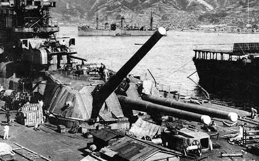
IJN Yamato under construction in September 1941
Carrier on the right is IJN Hosho and the store ship Mamiya is at the top of the picture
U.S. Naval Historical Center Photograph # NH 63433

.
Click here for additional photographs
.
.
Gun Characteristics
.
Designation Official Designation - 40 cm/45 (15.9") Type 94 (Model 1934)
Actual Size - 46 cm/45 (18.1")
Ship Class Used On Yamato Class
Date Of Design 1939
Date In Service 1941
Gun Weight 363,000 lbs. (164,654 kg) with breech
Gun Length oa 831.9 in (21.130 m)
Bore Length 815 in (20.700 m)
Rifling Length about 806 in (20.480 m)
Grooves (72) 0.181 in deep x about 0.478 in (4.6 mm x 12.14 mm)
Lands about 0.312 in (7.93 mm)
Twist Uniform RH 1 in 28
Chamber Volume about 41,496 in3 (680 dm3)
Rate Of Fire 1.5 - 2 rounds per minute
Note:  At the loading angle of +3 degrees, a firing cycle of about 30 seconds could be achieved.  However, this would equate to a range of no more than 6,560 yards (6,000 m).  The additional elevation and depression times required to reach an elevation of 41 degrees increased the firing cycle by about 11 seconds.  As can be seen in the Range Table below, most ship-to-ship actions would rarely exceed an elevation of 20 degrees, so an intermediate time of 35 seconds would seem to be reasonable for most battle-range engagements.
.
Ammunition
.
Type Bag
Projectile Types and Weights
(see Notes 1 and 2)
APC Type 91 - 3,219 lbs. (1,460 kg)
APC Type 1 - N/A
Common Type 0 HE - 2,998 lbs. (1,360 kg)
Common Type 3 IS - 2,998 lbs. (1,360 kg)
Bursting Charge APC Type 91 - 74.6 lbs. (33.85 kg)
APC Type 1 - 74.6 lbs. (33.85 kg)
Common Type 0 HE - 136 lbs. (61.7 kg)
Common Type 3 IS - N/A
Projectile Length
(see Note 2)
APC Type 91 - 76.9 in (195.35 cm)
APC Type 1 - 81 inches (206 cm)
Common Type 0 HE - 63.0 in (160 cm)
Common Type 3 IS - 63.0 in (160 cm)
Propellant Charge 794 lbs. (360 kg) 110 DC1
Muzzle Velocity
(see Note 5)
APC Type 91 - 2,559 fps (780 mps)
APC Type 1 - 2,559 fps (780 mps)
Common Type 0 HE - 2,641 fps (805 mps)
Common Type 3 IS - 2,641 fps (805 mps)
Working Pressure 19 - 20.3 tons/in2 (3,000 - 3,200 kg/cm2)
Approximate Barrel Life about 150 - 250 rounds
Ammunition stowage per gun 100 rounds
Notes:

1) IS is my abbreviation for the Type 3 Common incendiary shrapnel round (sankaidan) intended for AA use.  Fuzes for these were set in the shell handling room with fuze protectors used to prevent damage before loading.  Type 3 Common may have made up as much as 40% of the outfit by 1944.  See below for more information.

2) Type 91 shells were all 6 / [infinity] crh with boat tail.  The diameter of the bourrelet was 18.07 in (45.898 cm).  The original Type 91 APC was L/4.25 or 76.9 inches (195.35 cm) long.  The later Type 1 version was L/4.47 or 81 inches (206 cm) long.  The main difference was the length of the windscreen, as the conic angle went from 23.5 degrees to a longer, sharper 21 degrees.  Type 1 shells also introduced a dye bag, which may have slightly increased their weight over that of the Type 91.  The base of the Type 1 was slightly different from the Type 91 as the original two driving bands were replaced by a single double-width band with a copper ring in the middle of the band.  The modified type superseded the original in 1941, so these battleships may never have carried any but the newer shell.  See the additional photographs page for a sketch of the Type 91.

3) Each mounting held 300 rounds with 180 rounds stored in two handling rooms on the rotating structure and the remaining 120 in shell rooms.  The practice was to feed projectiles from the lower handling room until the supply was exhausted and then feed from the upper handling room.

4) The propellant charge was in six bags.  Bags were made of wool until 1942 at which time silk ones were substituted.  Bags had a 1.1 lbs. (0.5 kg) separate silk bag of gunpowder at one end.

5) Smaller propellant charges were available for training and target rounds.  These were designated as "Reduced" and "Weak" charges.  "Reduced" charges gave about two-thirds of the normal service velocity and were rated at 0.25 ESR while "Weak" charges were rated at 0.5 ESR.  No muzzle velocity is given for "Weak" charges.

.
Common Type 3 Sankaidan Anti-Aircraft Shell
.
As were most Japanese warships, the Yamato and Musashi were provided with a special anti-aircraft incendiary shrapnel shell officially designated as "3 Shiki tsûjôdan" (Common Type 3) and supposedly nicknamed "The Beehive," but this could be apocryphal.  This round weighed 2,998 lbs. (1,360 kg) and was filled with 900 incendiary-filled tubes.  A time fuze was used to set the desired bursting distance, usually about 1,000 meters (1,100 yards) after leaving the muzzle.  These projectiles were designed to expel the incendiary tubes in a 20 degree cone extending towards the oncoming aircraft with the projectile shell itself being destroyed by a bursting charge to increase the quantity of steel splinters. The incendiary tubes ignited about half a second later and burned for five seconds at 3,000 degrees C, producing a flame approximately 5 meters (16 feet) long.

The concept behind these shells was that the ship would put up a barrage pattern through which an attacking aircraft would have to fly.  However, these shells were considered by US Navy pilots to be more of a visual spectacular than an effective AA weapon.

.
Range
.
Elevation
With 3,219 lbs. (1,460 kg) APC
Striking Velocity
Angle of Fall
2.4 degrees
5,470 yards (5,000 m)
2,264 fps (690 mps)
3.3
5.4 degrees
10,840 yards (10,000 m)
2,034 fps (620 mps)
7.2
8.6 degrees
16,400 yards (15,000 m)
1,844 fps (562 mps)
11.5
12.6 degrees
21,870 yards (20,000 m)
1,709 fps (521 mps)
16.5
17.2 degrees
27,340 yards (25,000 m)
1,608 fps (490 mps)
23.0
23.2 degrees
32,810 yards (30,000 m)
1,558 fps (475 mps)
31.4
30.0 degrees
39,180 yards (35,830 m)
---
---
40.0 degrees
44,510 yards (40,700 m)
---
---
45.0 degrees
(max elevation
of turret)
45,960 yards (42,030 m)
---
---
48.0 degrees
46,050 yards (42,110 m)
---
---
50.0 degrees
45,790 yards (41,870 m)
---
---
Note:  Time of flight for APC Shell with MV = 2,559 fps (780 mps)
   18,410 yards (16,830 m):  26.1 seconds
   30,530 yards (27,920 m):  49.2 seconds
   44,510 yards (40,700 m):  89.4 seconds
   45,960 yards (42,030 m):  98.6 seconds
.
Elevation With 2,998 lbs. (1,360 kg) HE
Range @ 45.0 degrees 35,600 yards (32,550 m)
.
Armor Penetration with 3,219 lbs. (1,460 kg) APC
.
Range
Side Armor
Deck Armor
0 yards (0 m)
34.01" (864 mm)
---
21,872 yards (20,000 m)
 19.43" (494 mm)
 4.30" (109 mm)
32,808 yards (30,000 m)
14.19" (360 mm)
7.43" (189 mm) 
Note:  This data is from "Battleships:  Axis and Neutral Battleships in World War II" for a muzzle velocity of 2,559 fps (780 mps) and is based upon the USN Empirical Formula for armor penetration.
.
Range
Striking Velocity
Side Armor
Deck Armor
Angle of Fall
21,872 yards (20,000 m)
1,713 fps (522 mps)
 22.28" (566 mm)
 6.57" (167 mm)
16.5
32,808 yards (30,000 m)
1,558 fps (475 mps)
16.38" (416 mm)
9.06" (230 mm)
31.4
Note:  This data is from "Anatomy of the Ship:  The Battleship Yamato," but has been corrected for typographical errors in that publication.
.
Mount / Turret Data
.
Designation Three-gun Turrets
   Yamato (3)
Weight  2,730.2 tons (2,774 mt)
Elevation -5 / +45 degrees
Elevation Rate 10 degrees per second
Train about +150 / -150 degrees
Train Rate 2 degrees per second
Gun recoil 56.3 in (1.43 m)
Loading Angle +3 degrees
Notes:

1) These mountings had a unique sliding cross-head for the elevating cylinder anchor point.  This could be set to allow either -5 to +45 degree elevation or +3 to +41 degree elevation.  The advantage of this was that the latter setting meant that no locking pins had to be inserted to hold the guns at the loading angle, the operator merely kept the controls at the "depress" position until an indicator showed him that loading was complete.  This sped up the loading cycle and, as shown in the range table above, cost very little in terms of maximum range.

2) These turrets had two independent sets of training gear, only one of which was in use at a time.  Each was driven by a 500 hp vertical swashplate motor driving a train of straight-toothed pinion gears.  Guns were individually sleeved.

3) The gun axes were 137.8 in (350 cm) apart.

4) The center gun had a 0.080 second firing delay to reduce shell dispersion.

5) Each gun had its own pusher shell hoist and cordite cage hoist.  The cylindrical flashtight charge container held all six charges in line, allowing a single rammer stroke to load the gun.  Two auxiliary hoists were fitted in each turret.  Both shells and propellant bags were hoisted vertically in suitable containers.  Transfer of shell in the gunhouse was effected manually by overhead travellers and chain purchase.

6) The following excerpt is taken from US Naval Technical Mission to Japan report O-45(N):

The 46 cm (18-inch) triple mount was the first large mount ever designed and produced by the Japanese which was not practically identical with the large British mounts prior to World War I and built for the battleship KONGO.  In almost every part of the 18-inch mount a complete departure from this old design was made.  For shell and powder hoists the Japanese 18-inch mount was copied [sic, but probably meant 16-inch mount], but, generally speaking, the mechanisms were unique.  Compared with British and U.S. practice, (16-inch, 14-inch and 8-inch), the mount was simple in design.  It had no complicated hydraulic safety interlocks and comparatively few mechanical ones.  Reliance was placed on good drill to avoid accidents.  Even taking into account the size of the gun, the general impression gathered is that an unduly large factor of safety had been allowed in the design of the turret machinery as a whole, resulting in a very heavy mount, the total revolving weight of one turret being 2,510 metric tons [2,470 tons].

A very satisfactory rate of fire was obtained for a gun of this size:  1.5 rounds per minute at full elevation.  A maximum range of slightly under 46,000 yds was obtained with a 3,220 lb shell.

The most interesting features of the mount were (a) the method of stowing and moving shells about the shell and shell-handling rooms using a fairly simple, but bulky and heavy mechanism; (b) the powder cage and rammer, designed to enable a full charge to be loaded by a single rammer stroke; and (c) the attachment of the elevating piston rod to the slide which was designed to avoid the necessity for a complicated slide locking gear, and to reduce the loading cycle time by cutting out the time usually required for locking and unlocking the slide.

Other mechanisms worthy of note are as follows:

    1) The powder bogie and mechanisms for transferring powder from the fixed to the moving structure.
    2) The gunhouse bogie and rammer.
    3) The wormless training gear, with its "coaster" gear substitute for the normal friction discs.
    4) The electric cable leading-in gear.

It was stated by the Japanese that considerable attention had been paid to flashtightness throughout the turret.  Although this was probably not up to U.S. and British standards, it is difficult to give a definite opinion on this point without having seen a completed turret.  The performance of the turret in service was considered by the Japanese to have been very satisfactory with the exception of the large quantities of lubricating oil, which the Japanese could ill afford, were required by the training and powder hoist gears.  Spreads of salvos were reasonably small, (about 500 to 600 yards at maximum range).  The blast effect, particularly on the bridge, was found to be very severe.

Without having seen one of these turrets in operation or even a completed turret, an opinion will not be expressed on its probable performance or its value as a weapon beyond that already given above.  The statements of the Japanese, however, are considered to be well-founded.

.
Data from
"Naval Weapons of World War Two" by John Campbell
"Battleships:  Axis and Neutral Battleships in World War II" by W.H. Garzke, Jr. and R.O. Dulin, Jr.
"The Big Gun:  Battleship Main Armament 1860-1945" by Peter Hodges
"Anatomy of the Ship:  The Battleship Yamato" by Janusz Skulski
---
US Naval Technical Mission to Japan report O-45 (N):  Japanese 18" Gun Mounts
US Naval Technical Mission to Japan report O-19:  Japanese Projectiles General Types
---
Special help from Mike Connelley, Nathan Okun and Richard Worth
Page History

23 April 2007 - Benchmark
27 May 2012 - Updated to latest template
08 January 2013 - Added note about incomplete guns